Monday, 14 December 2009

City Strata


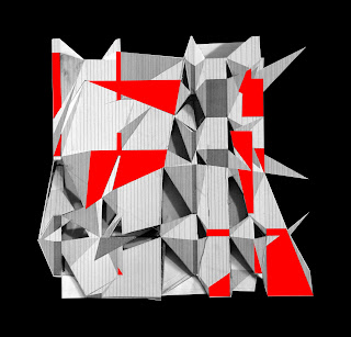
The city strata was derived, through a desire to create new forms of urban living, in which citizens are lifted above the existing city (therefore multiplying the ground), and into an environment which has the characteristic qualities of the most dense urban cities, such as vibrancy and a dichotomy of spaces. This offers citizens a heterogeneous environment, which promotes mobility over stasis, complexity over formalism and social interaction over segregation. Embracing the unpredictable and chaotic growth, that is characteristic of the most vibrant urban communities.


Tuesday, 1 December 2009

Diagrammatical plan analysis


Plan analysis- after breaking an area of the eighty sections into L-shaped components, the model was cut horizontally at various heights to assess the implications of the plan.


The following diagrams document this development in a concise manner, to enable the spatial implications to be better considered.


The first of these diagrams (above) illustrate the plan of the striated structure at 16m (top) and 12m above ground level.


Commonalities were then identified in the shades of each section, where they connect to the next. The diagram above illustrate the result of this.


These commonalities were then seperated from the plan and were considered as being various types of programme and circulation (both internal and external).

The diagram above shows the areas where programme connects from one storey to the floor below. These areas could therefore contain programme that requires multi-levels. The programmtic layout was developed with the desire to maintain the striated nature of the structure.


Possible programmatic configurations were then considered.


The diagrams above and below illustrate the stages of this, including locating similar programmes based on a common activity, such as living, sleeping, work, and recreation:


Moveability and circulation are vital to the concept of a universally accessible space. By locating certain programme towards certain areas, the project was able to ensure that users will only travel into areas that are appropriate to their needs. For example, a member of the public will be able to access more private spaces, but due to their location in areas of other more public programmatical components, they will not need to venture further to find these (below).


The diagram below illustrates internal (grey) and external (white with black outline) circulation areas:


Wednesday, 25 November 2009

Internal development


Above: 3D model of proposal
Below: sectional development


1. Vertical circulation areas
2. External horizontal circulation
3. Internal horizontal circulation
4. 5. 6. Programme / density of space / high or low spaces / dark or light atmosphere / floors

Identifiable problems: light, oppressive spaces that may be created, how to connect vertically, way finding (possibly through strip and pillar light wells)

Benefits: connection of spaces, horizontal circulation, variety of spaces.


Sunday, 22 November 2009

80 Sections


Programme and massing models

The pattern was related to the site by altering the structural grid lines. This created alterations in the various units. Consistencies within the pattern were then identified as being strips of programme that inhabit the site. These are highlighted in the lower diagram:


The system was then reflected in a three dimensional model, which was formed through strips of various thicknesses. These sections were extruded in a similar manner to the models illustrated in the previous post. The scale derived from observing other structures within the surrounding context:


In the next stage of this process, i reverted back to the thinner 2mm sections. In total, this equated to 80 individual laser cut sections for the entire site model at 1:500 scale, measuring 1200mm in length and approximately 150mm in width. From this it was easier to identify areas of higher density and coincided with the principle of erosion. In form, the model appears to be a 30m high block which has gradually eroded down, quicker in certain areas.
In contrast to the previous model, the sections are mirrored in order to create two levels of external circulation. Main existing routes are considered and new ones created. The model creates dichotomy of space, and variety for the users, increasing the possibility of chance encounters. The combined mass is viewed as a mass of combined structure, with one section connecting to the next:


For consideration: internal organisation, circulation from east to west, break the linearity, spatial and programmatic implications of the system, adapt current model.

Sunday, 15 November 2009

Metastadt Bausystem- by Richard Dietrich


Metastadt was designed by architects Richard J. Dietrich and Bernd Steigerwald in the 1960s, as a response to the urban sprawl of cities which appeared to be growing at an alarming rate. It was a modernist utopia, designed to be built over existing urban spaces, by incorporating highways, parking, and could bridge over existing highways.


The system incorporates everything a citizen could require, such as leisure facilities, museums, retail, public spaces, and hundreds of residential units. All of these functions would be located within a rigid modular grid 4.2m x 4.2m and 3.6m in height. Each module could be open and connected, or separated using moveable and interchangeable walls, ceilings, and façade systems, all of which could be altered to allow for maximum flexibility and future growth.


The structure was a steel rigging system, made from prefabricated steel components, which made up the individual modules.


Dietrich’s ambitious claim was that the Metastadt would alter the role and purpose of the architect, because having once designed the metastadt (the ideal future of city living), other forms of design would become irrelevant and outdated.


Following the construction of a prototype in Munich, a second Metastadt was built in Wulfen in 1974, containing 102 apartments, as well as shops, cafes and restaurants. However, in the 1980s the building began to falter as major stores began to move out of the arcade. The building became derelict in 1986, but 10 million DM were injected into the scheme as a final rescue effort the following year. However, following the discovery of major structural defects, the building was demolished.


Dietrich was born in Munich in 1938, which has been the location of most of his realized projects. He is also known for his bridges, which include the stressed ribbon bridge over the Main-Danube canal.


Tuesday, 10 November 2009

Erosion


Natural landscapes formed through predictable patterns of wind, water and other elements colliding with the earths surface. These include weathering, abrasion, corrosion, and dissolution. For example:


Durdle Door- England (photograph by Dave Hayward)


The Grand Canyon:


Unknown locations:


Monday, 9 November 2009

Layers of the city


The following model evolved through a combination of firstly the lessons that were learned from the previous model, and secondly through the creation of several simple rules at various stages of construction:

Principles from previous model: heights of various components, density of spaces, light and dark conditions

1. The lightest component areas were cut from the pattern (as can be seen from the images of the previous model, these cuts were taken from areas where the sections dispersed and where spaces began to connect and overlap to create open areas)


2. A lower level was created around these cuts to form apertures to a lower level, to create a fully connected and unobstructed space:


3. Cutting into the ground:


4. The darker components of the pattern were extruded to the maximum height of the previous model, which reflected the large masses that dominated the various sections:


5. Darker components that overlap the lower level were extruded also but only to half the height of the larger masses, to allow for more light into the lower level:


6. The various masses were then connected by creating horizontal planes which overlapped the corresponding components of the pattern below (some of these form the top of the lower level extrusions):


7. The remaining components of the pattern were then represented by more horizontal planes at lower levels. Those components which did not connect masses together became ramps from ground:


Like so: